Fun little project 🙂
The issue: Xavier, our second Citroen C6 had an issue with the right hand side (passenger) mirror. The folding worked flawlessly, but the dipping and raising of the mirror was not. In order to get the mirror in position, you had to push it manually, as the electronic control of the mirror was ¨dead”/ stuck. Minor inconvenience, as it was not causing any problems while driving, but having the mirrors automatically adjust when reversing or being able to adjust to each driver´s preference was something that we missed.
We had the following error in diagnostics:
“CC02: Mirror mechanism sensor input fault. Characterisation: Open Circuit. ”
Figuring out the part number:
First I checked various websites to figure out the part number: #660237. This is the round little assambly of 2 motors that move the mirror into desired position. Of course when citroen database was checked by our mechanic, this part was “not available”…
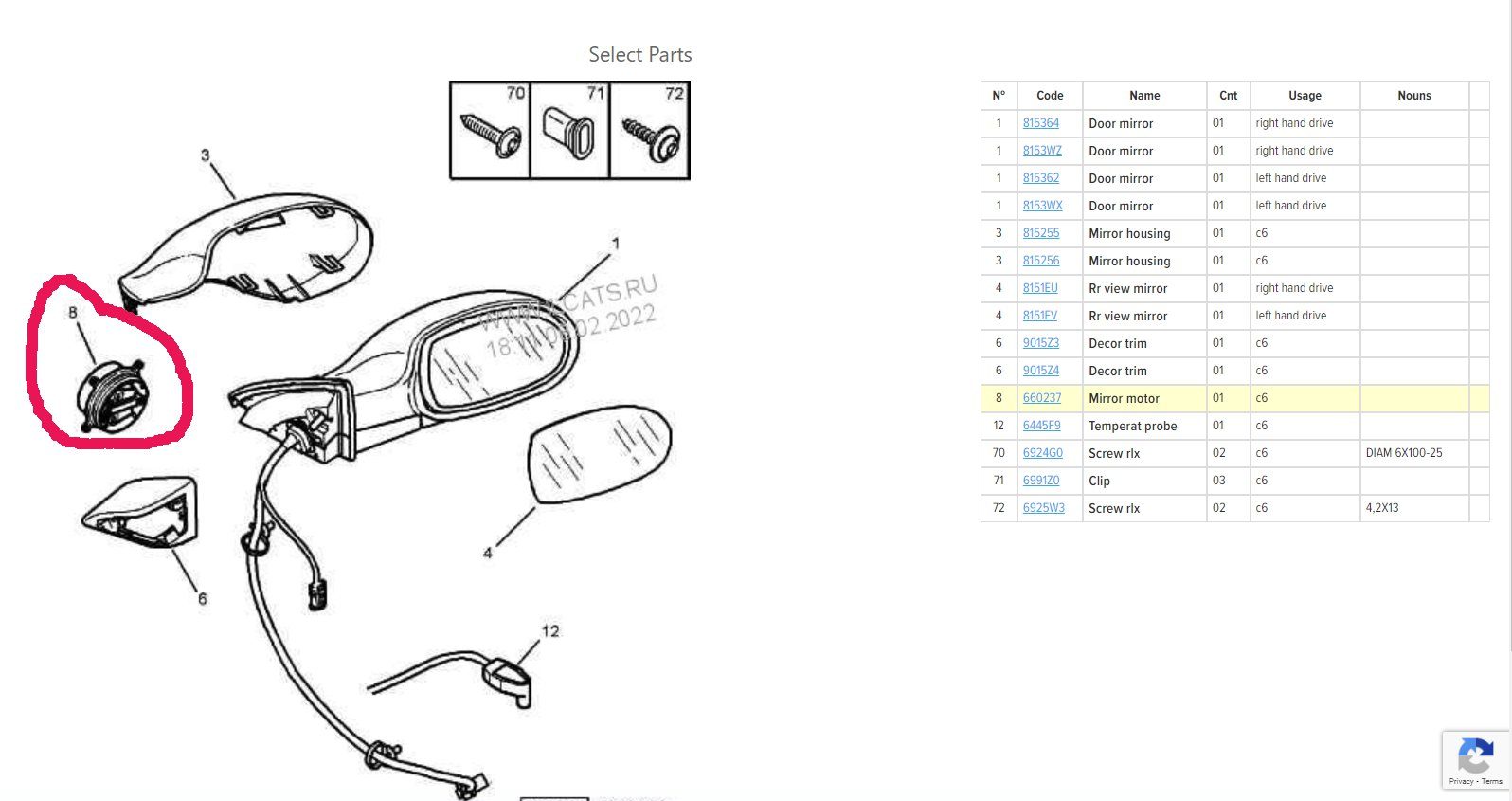
Since Xavier is a long term project with other major issues to be fixed first, this mirror dipping is really low priority and at this moment we didn´t wanted to spend to much money on it, so buying an original replacement or the full second hand mirror was out of the question because of the prices:
Citroen C6 Front Door Exterior Mirror Adjusting Motor (660237)- RIGHT MIRROR CITROËN C6 (TD_) 2.7 HDI – BP2667781C27
- Wing mirror, right with part number 8153WX Used
Ebay, original parts -100 euro+ shipping
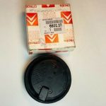
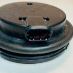
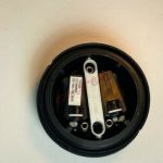
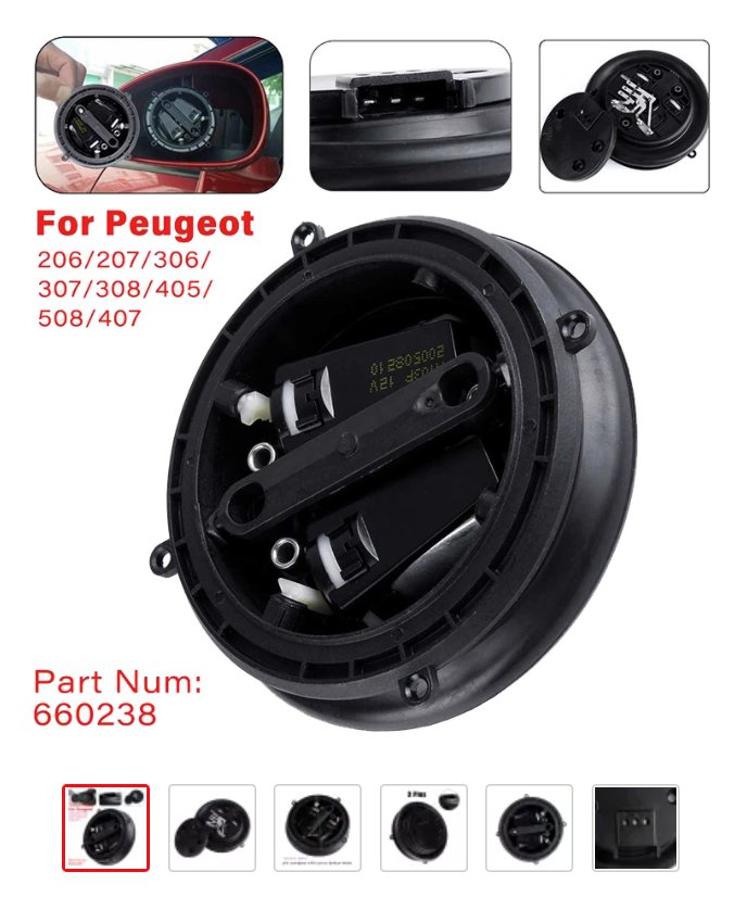
These are the photos from the ebay listing, I thought you may want to see how the original part and package looks 😀 Wish I had access to this because it´s obvious, there are more than 3 pins in the connector in the original one. (8)
Initially I thought either the electronics or the little motors might be broken, or some contact issue. I didn’t wanted to disassemble the mirror and wait 3 weeks until the replacement part arrives, so we ordered one that looked fairly similar with the drawing. I was actually hoping to just be crazy lucky and get the issue fixed cheap. After all the part number was almost the same LOL. 660238 instead of the 660237. Was a big maybe, but was worth the try.
In meantime, I looked up some tutorials on mirror issues, and I found this facebook post on C6owners. (This is a private facebook group, so you would need to join to see the content… it explains well what needs to be done, cleaned.)
This is how I removed the mirror:
took a medium size flat head screwdriver, pushed the top of the mirror to turn it gain access to the bottom part and pushed my flat head screwdriver in, trying to release more clips. Finding the first one was the hardest, after this was easy to just go around and unclip them. I just hoped I won’t break any plastic bits when trying to remove the mirror itself. After the mirror was out, removing the motor was really easy, only 3 screws and unpinning the 8 pin cable from the bottom.
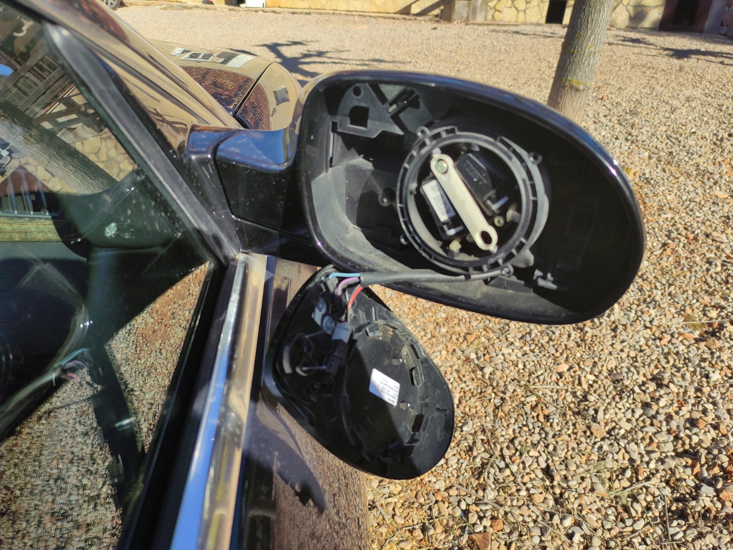
Pic from C6owners, Simon M.E. with the clip that needs unclipping.
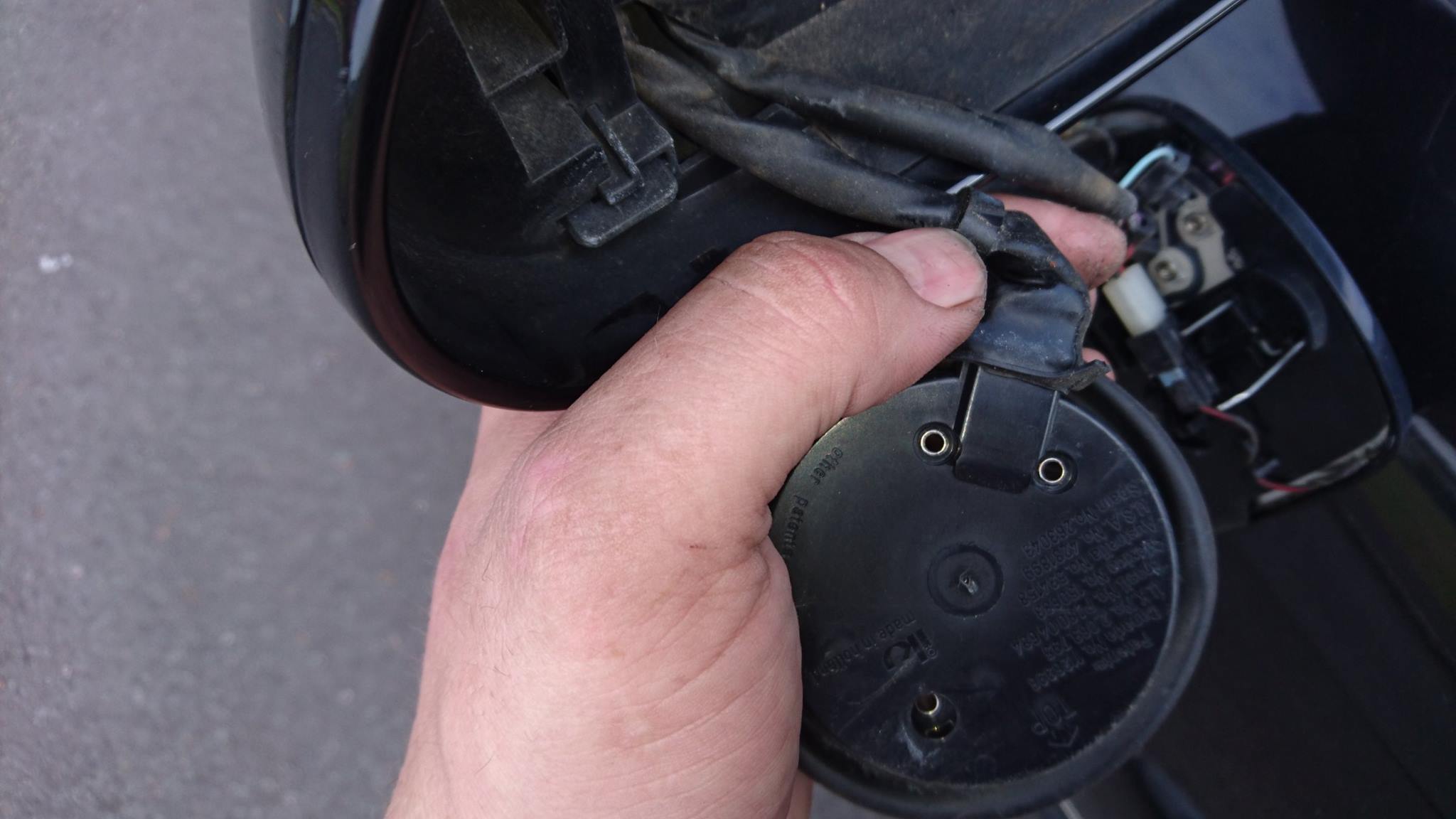
Mirror secured back in place until the repair was carried over.
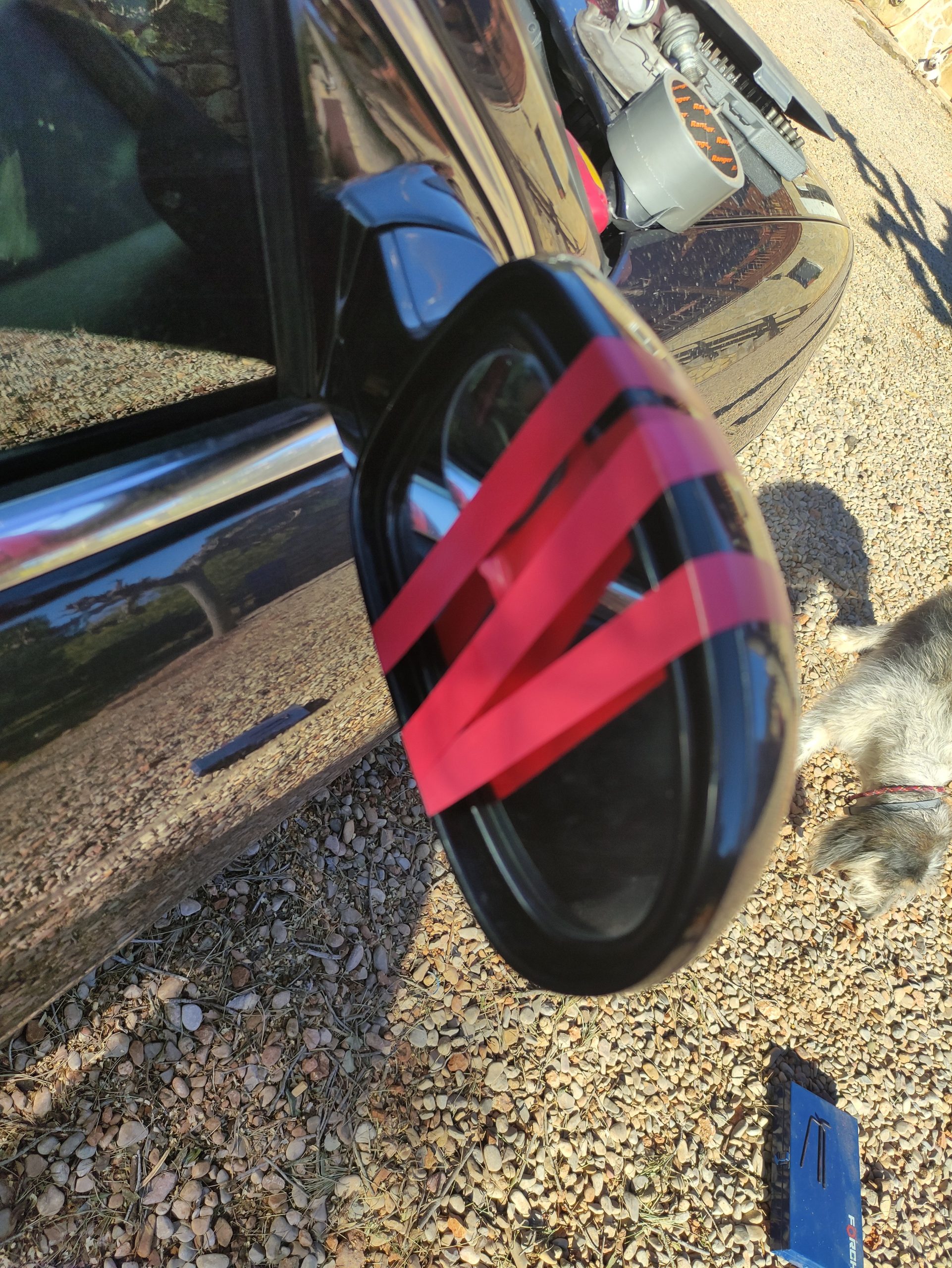
Step 1, (following the tutorial of Simon) snap the little black pastic tab with a small flathead screwdriver:
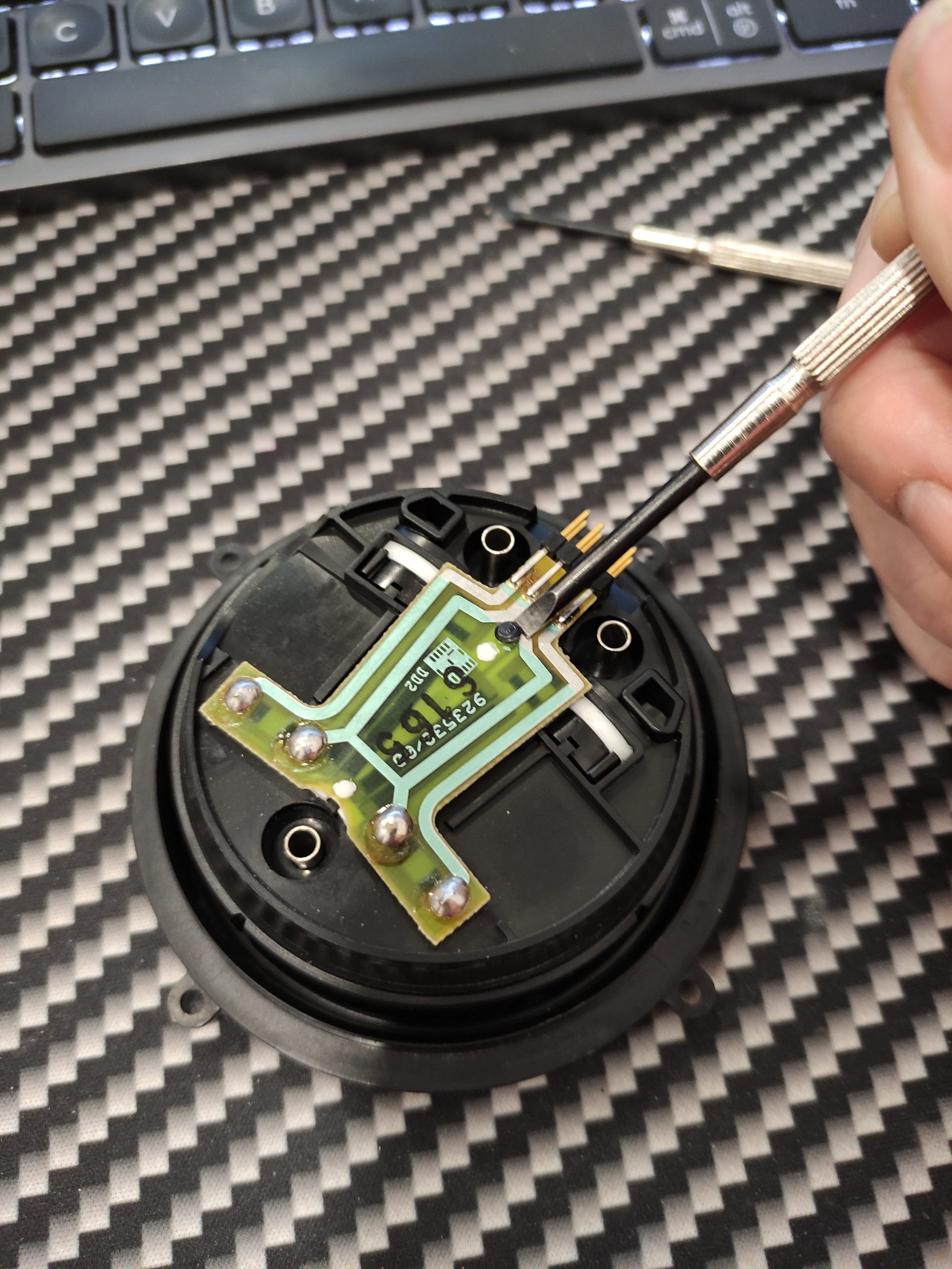
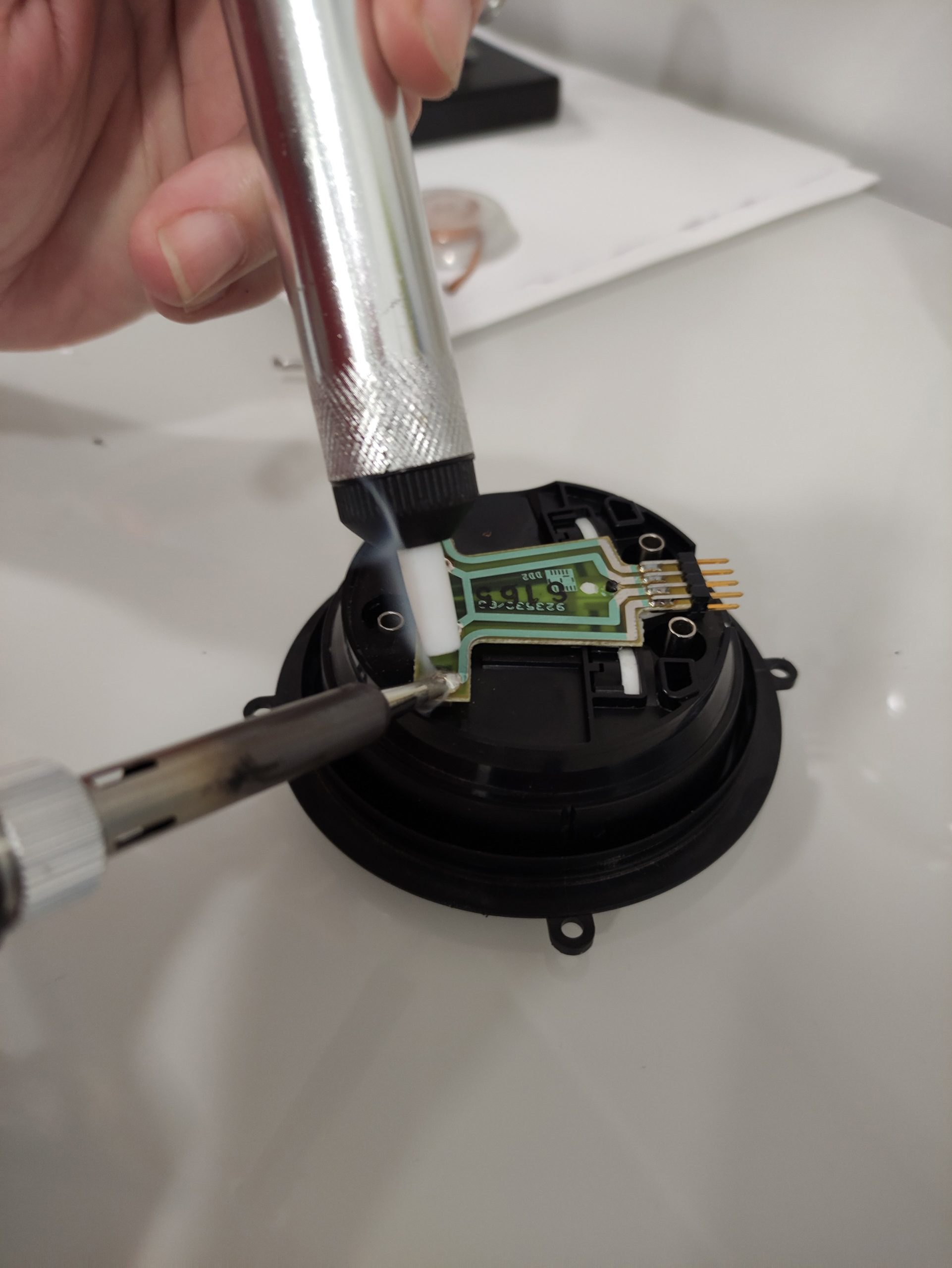
Step 2 – unsolder the 4 motor connectors
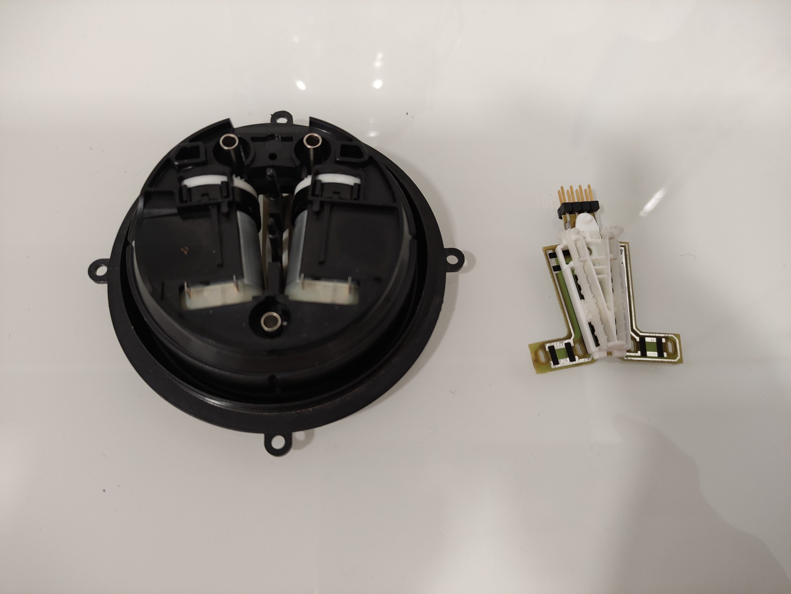
Step 3 – remove the small printed circuit board – and turn it upside down
there are 2 small potentiometers and 2 plastic “screws” (I think those are called worm drives?)
Step 4 Instructions from the tutorial by Simon: “with the pcb printed side down test for resistance between the top 2 pins on each of the potentiometers should be around 2.5 to 3 k ohms”
carefully remove the worm drive gears to get to the potentiometers below them (image source: Simon):
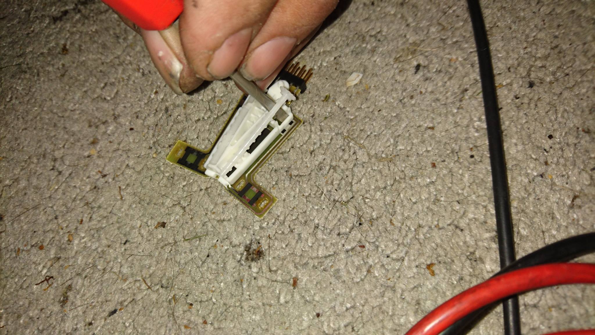
use switch cleaner or meths and tip some on the carbon track then slide the potentiometer slider back and forth a few times
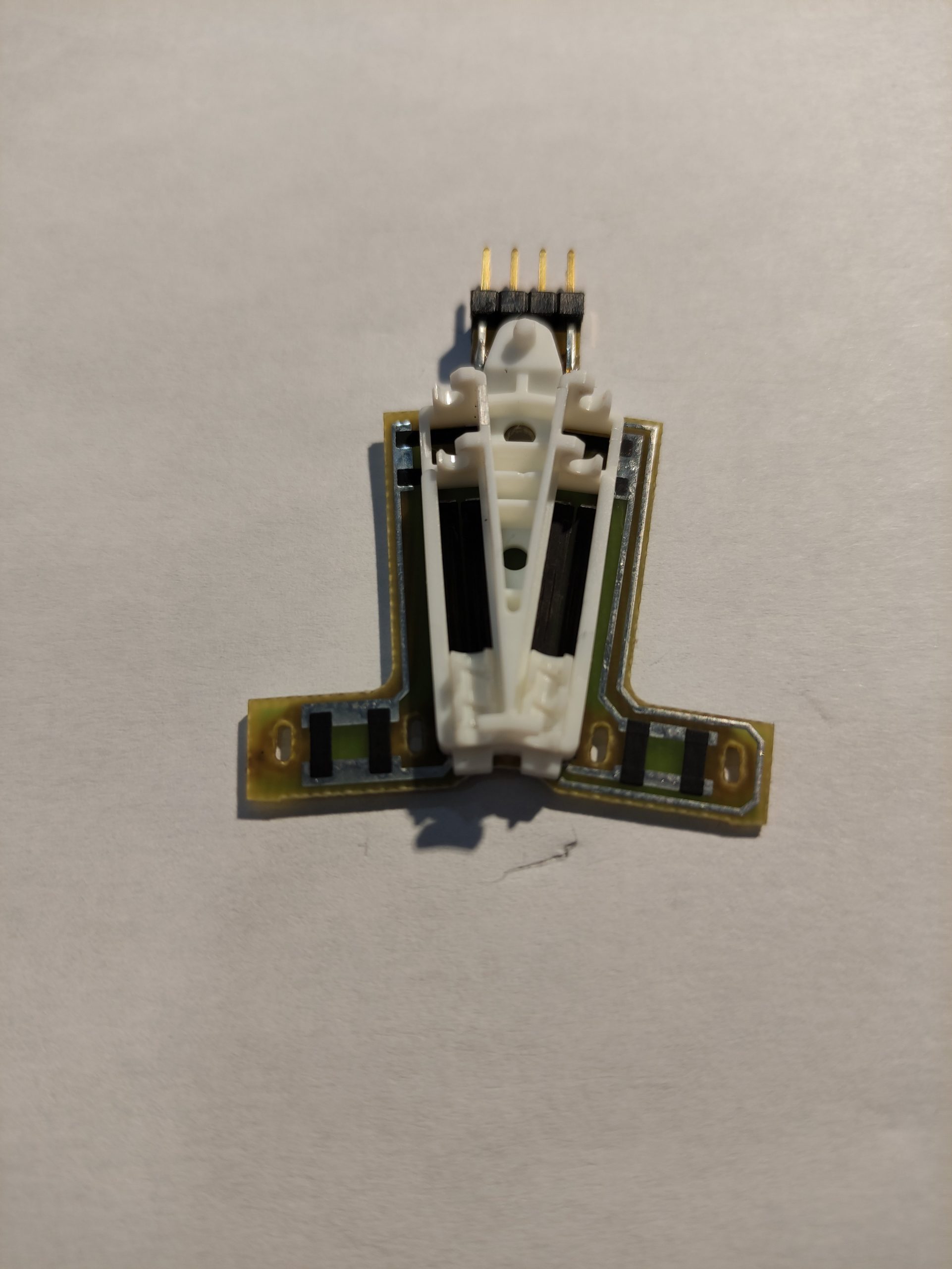
I removed both sliders carefully. One of the little contacts was displaced on one of the sliders, but I was able to gently push it back to it´s place.
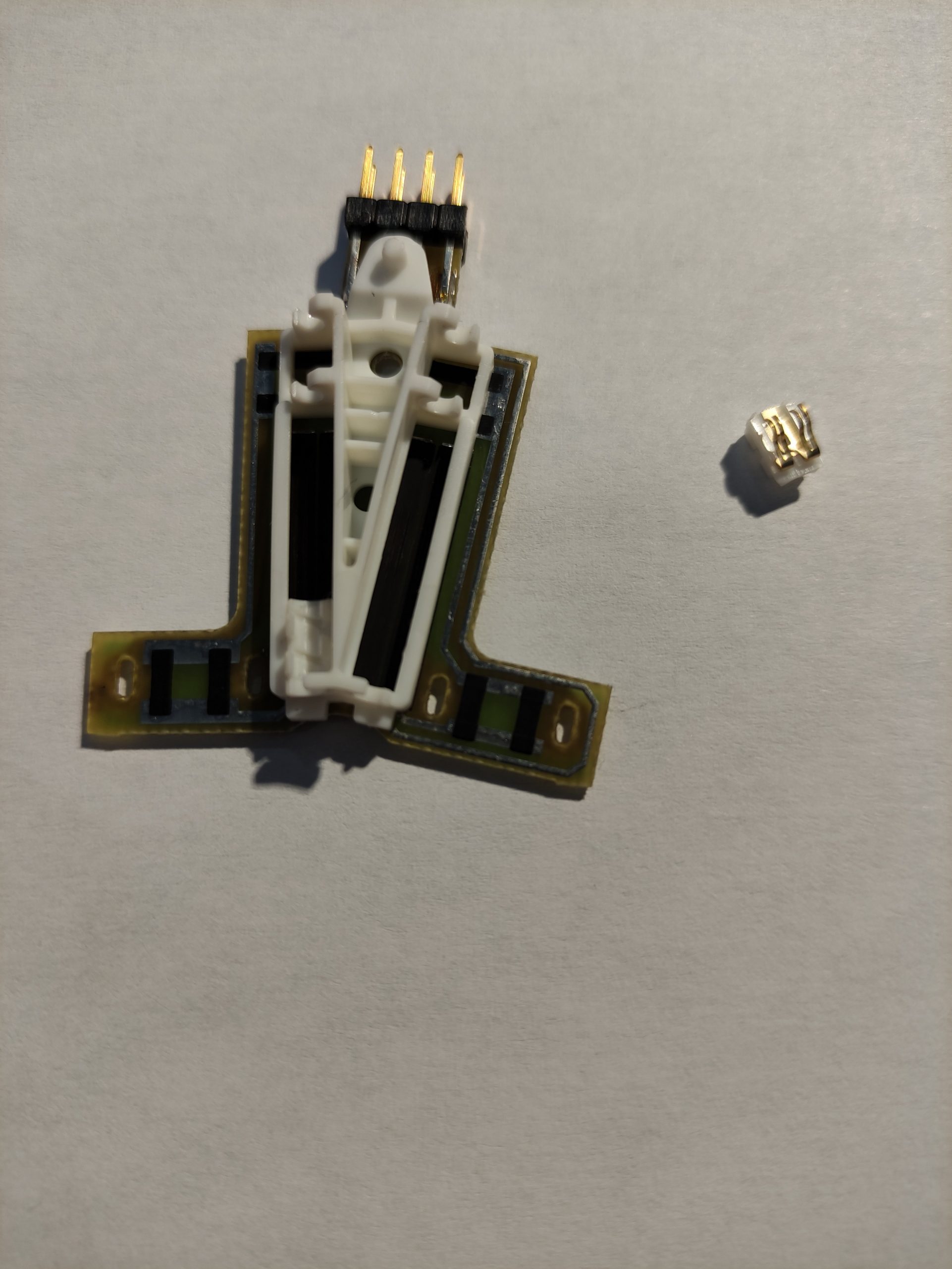
next I put the sliders back, pop the worm gear back by inserting the end opposite the gear and pop back in carefully
then with the pcb with the potentiometers facing you check the resistance of the outer pins each side read the correct resistance around 3k ohms
When putting back the potentiometers and the worm drive, I had a bit of dilemma: what position should they be? Some in the facebook group suggest to mark/ make photo or just remember the initial positions of the potentiometers so you don’t confuse the mirror, but I also moved the whole assembly when I applied the 12V. So I figured if move the little motors so the whole assamebly is as “centered” as possible, and make sure the potentiometers are also centered… I should be fine. (phiew was ok like this)
After this I assembled the whole thing back, first by soldering the 4 pins, than adding (melting) a little plastic to keep the PCB in place.
You may wonder what happened with the other, cheappart 😀
This.
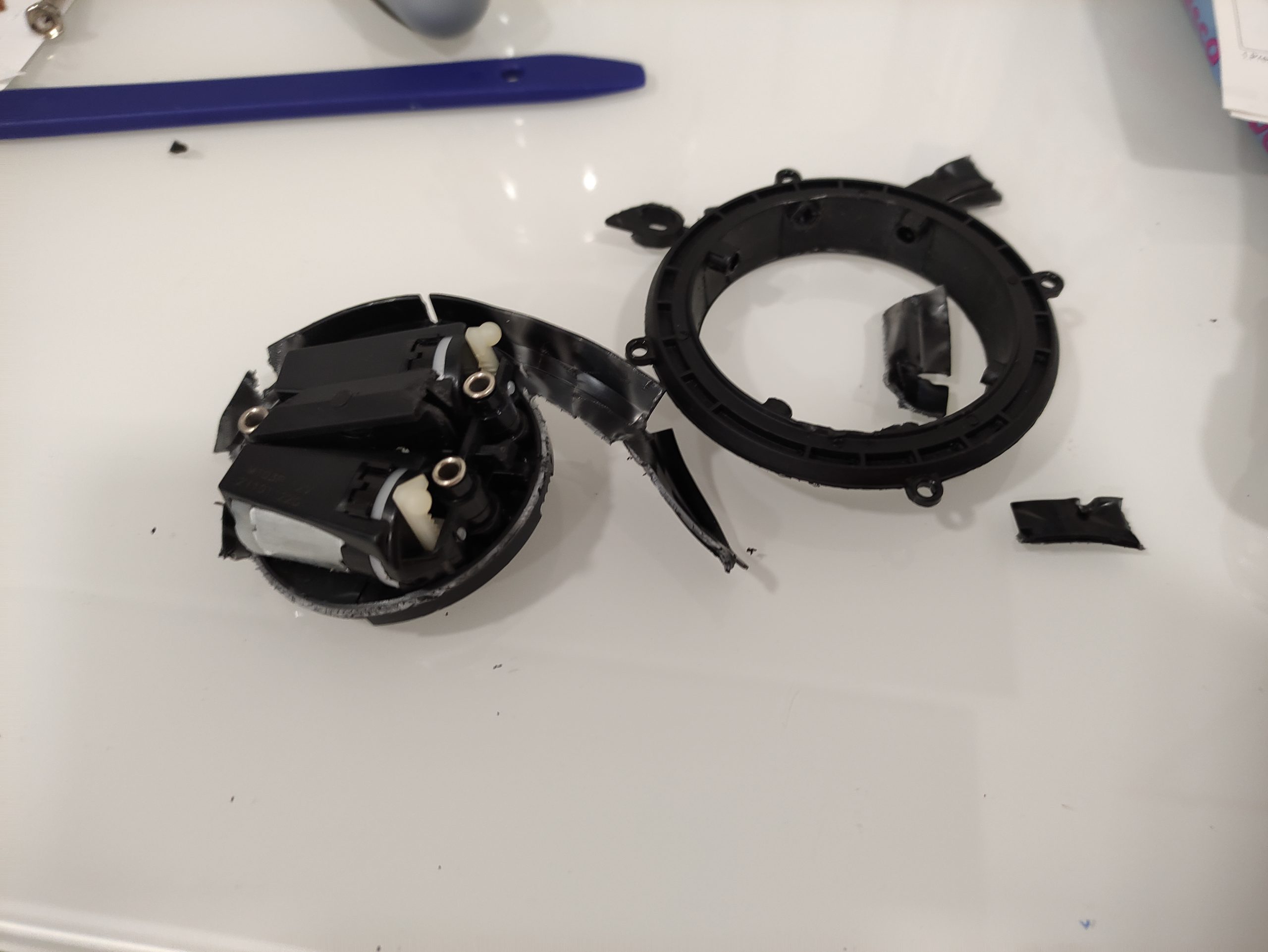
Although it may look tragic, this part actually helped me to understand how the plastics were put together. I could open it without any worry of what will break, as the black plastic exterior was completely unusable anyway. This way I managed to avoind breaking the good part!
One of the big challenges was to get out the “transversal” white “beam”. It requires 2 steps to be removed. First a gentle push with a flathead screwdriver from one of the sides where it connects with the black trim. My biggest worry whas that I am going to break the little part that connects it with the black side.
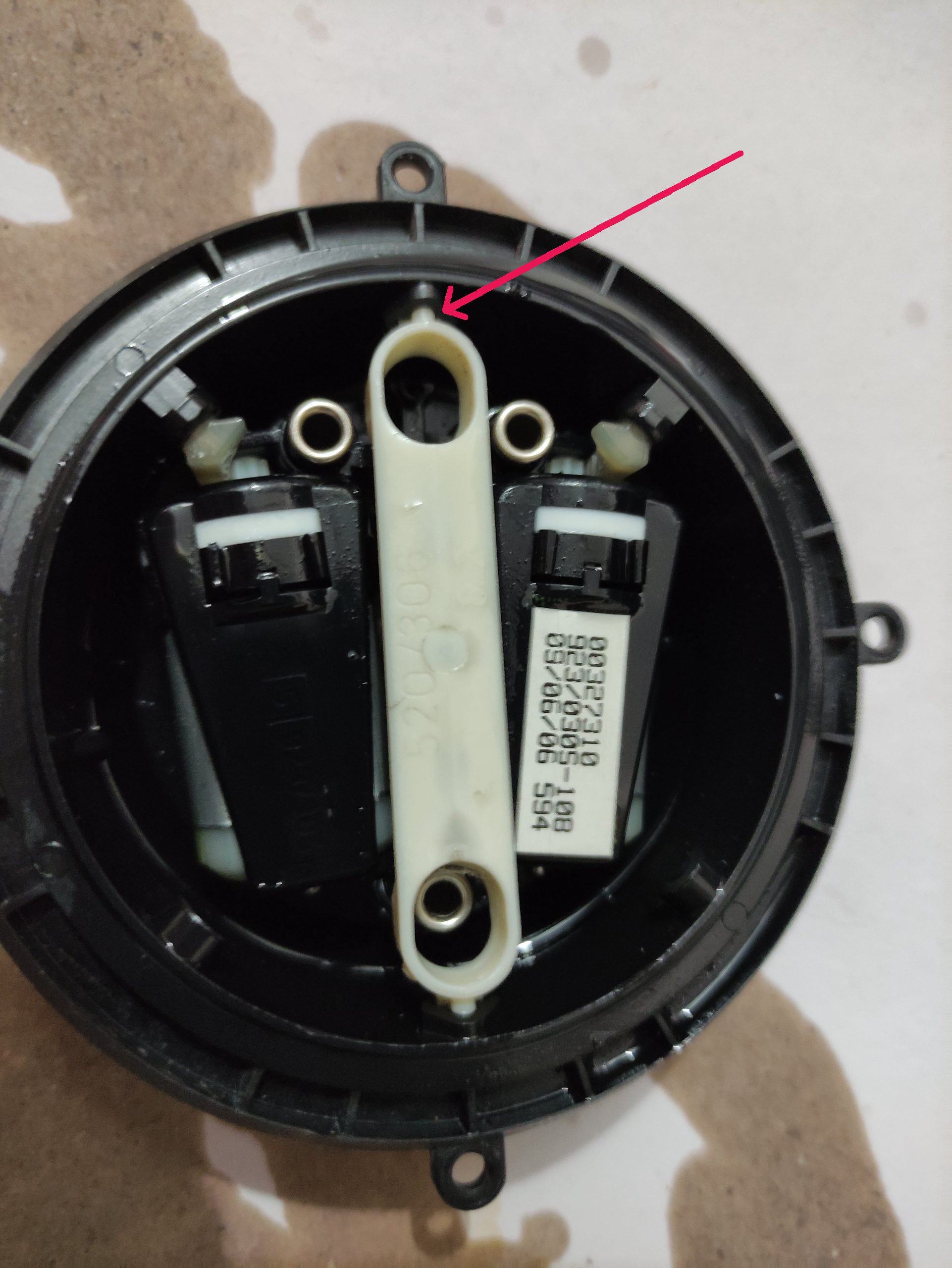
Than turn the whole thing over and with a small flathead screwdriver try to sort of unclip the “beam” -in the center. Don’t forget to be extra careful and gently. You need to apply a certain force in order to get it open, but not to much, or everything will break.
When I installed back the worm drives, I adjusted the potentiometers in the center, and the with 12, adjusted the little drive to be “balanced” in the middle. 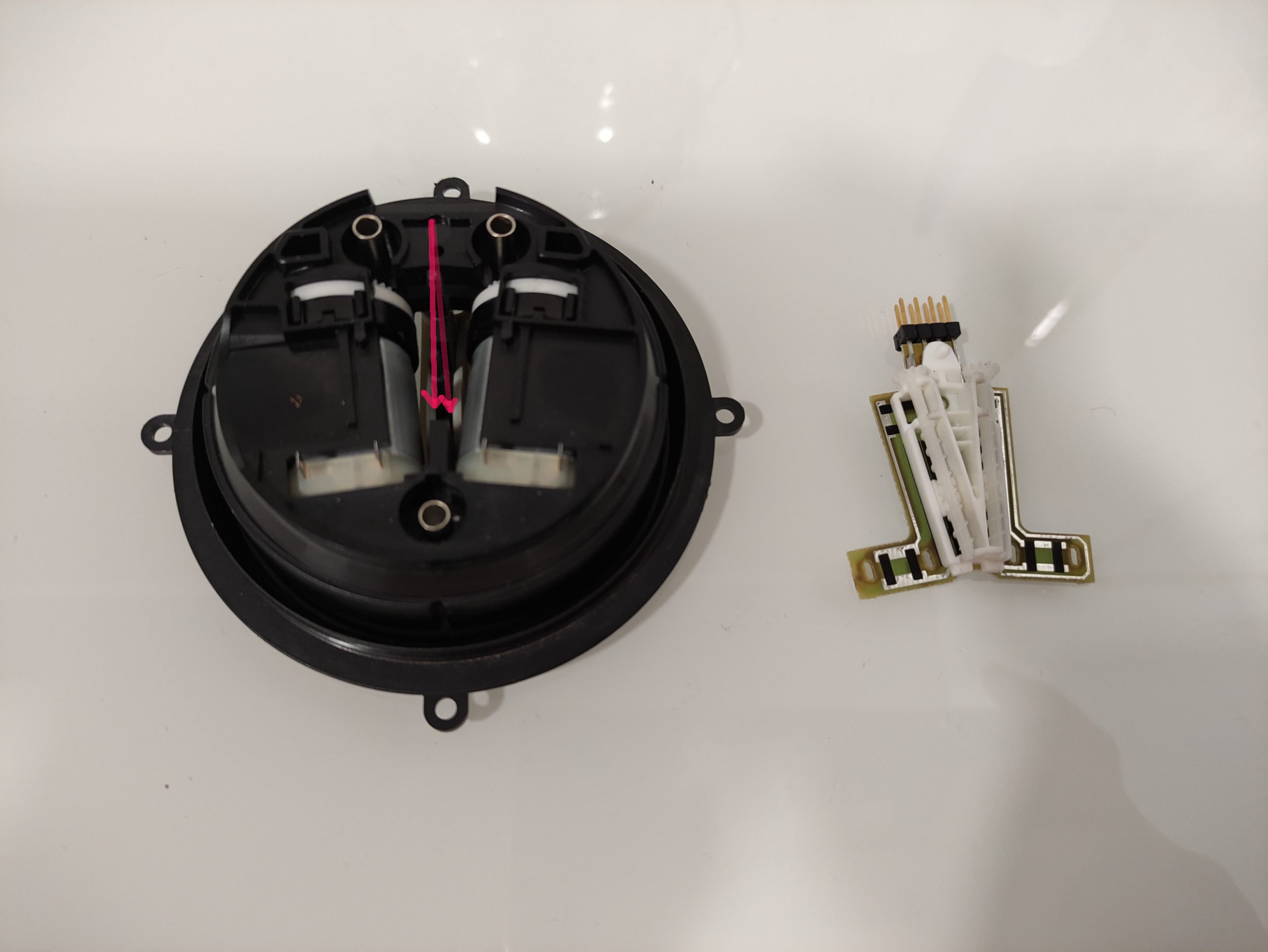
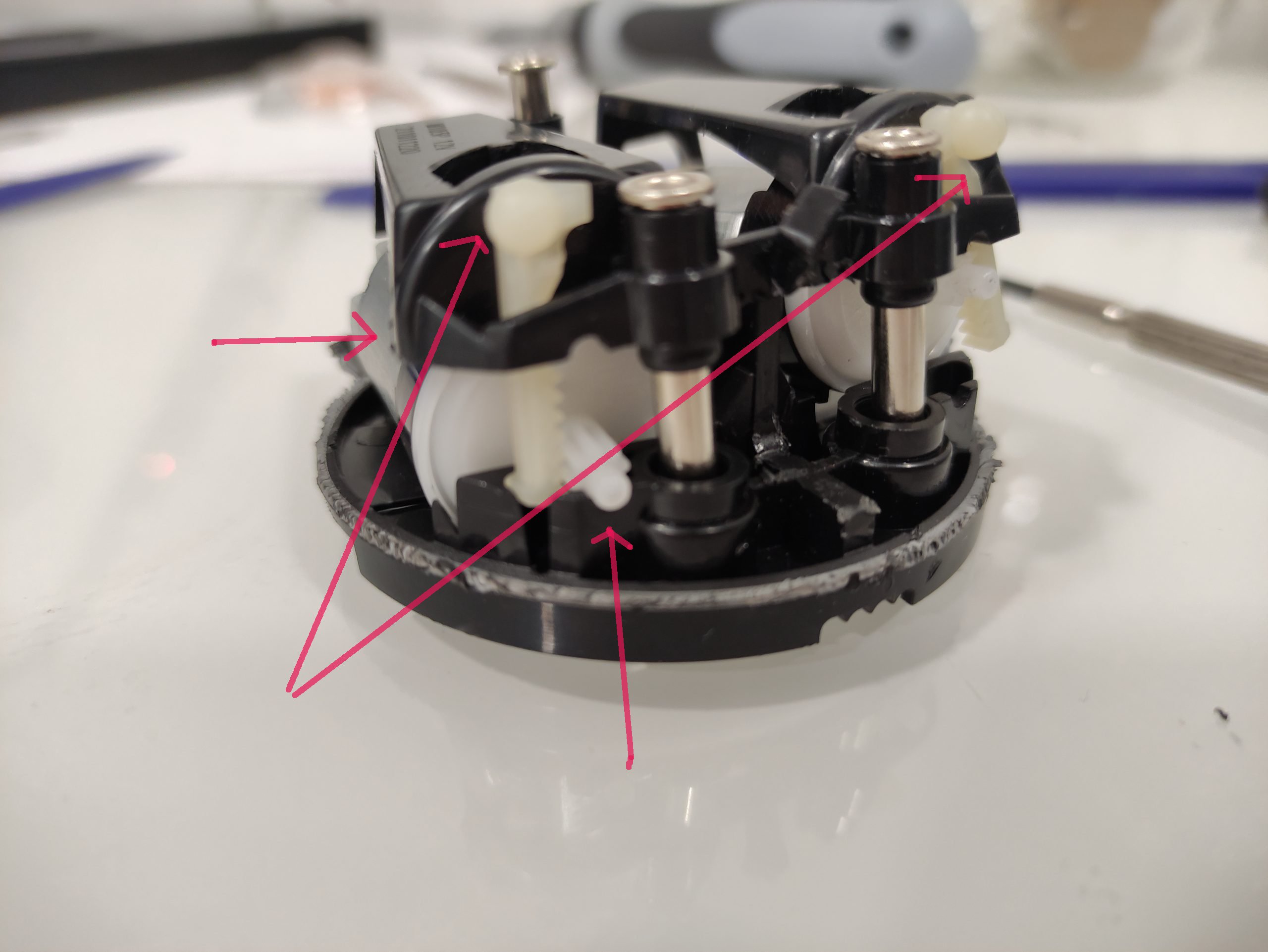
These small bits marked with arrows are exactly the same: the little gear on the motor, the other gear that connects to the black plastic body. and the small motor as well.
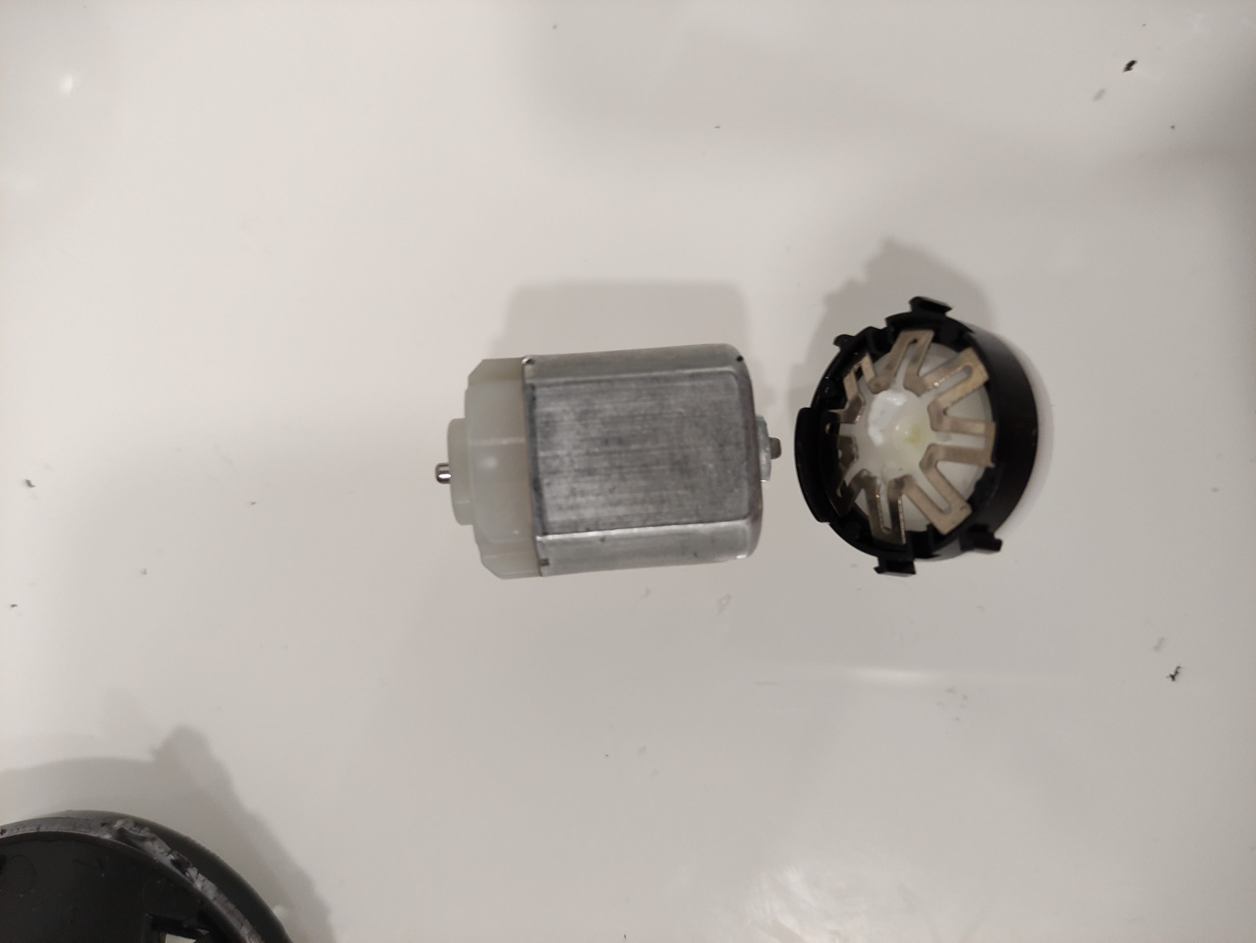
I saved the usable parts, because who knows one day one of the little motors may fail, and I will just change them 😀
Note: the #660237 motor is same for each side
Tomorrow is the big day 🙂 to see if it actually works 😀
Update: the mirror motor is working, it can be adjusted with the buttons now.
